MAT162 Example 4:
Local-Global MAT162-MAT054 Impact on
Elliptical Pressure Vessels with Internal Pressure
Impact on composite pressure vessels for space applications such as Z-2 Space Suit composite components (Fig. 5, Ref. [1]) require the use of progressive composite damage modeling for impact critical designs. A local-global MAT162-MAT054 (solid-shell) impact analysis methodology had been used to capture the energy dissipating damage modes under the impactor using MAT162 and solid elements. For space applications, the pressure vessel is internally pressurized thus all impact simulations shall have internal pressure load applied first followed by the impact event. In this example, the local-global modeling and analysis methodology is presented.
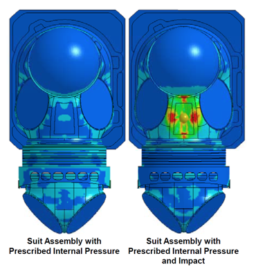
Figure 4.1: Arbitrary Stress Contours of the Space Suit Assembly with Prescribed
Internal Pressure and Impact Loading Conditions (Fig. 5, [1]).
Finite Element Modeling
The complex curvature of the Z-2 space suit is modeled as a cylinder with elliptical cross-section. Figure 4.2 shows the finite element model where two solid metal rings are used at the two ends, the central impact zone is modeled with 3D solid elements while the cylinder ends are modeled using 2D shell elements. A solid sphere is modeled as the impactor. The impactor can be parametrically placed at any angle on the mid-section of the cylinder, and the impacts can be defined as normal or oblique to the cylinder surface. In this example four through-thickness solid parts have been used to define three T-T delamination planes. Note that the transverse deformation and damage cannot be modeled accurately without modeling T-T delamination. The intersection of solid and shell elements are node merged, however, additional constraints can be applied as well. *MAT_162 is used for the solid elements, and *MAT_054 is used for the shell elements. Material properties for unidirectional (UD) T650/5250-5 Carbon/Epoxy composites provided by Materials Sciences Corporation (MSC) has been used in the simulations.
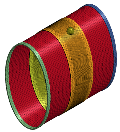
Figure 4.2: Local-Global Solid-Shell (MAT162-MAT054) Finite Element Model of the
Elliptic Cylinder subjected to Internal Pressure and Transverse Impact.
 |
 |
Pressure Loading Conditions
A ramp pressure load is applied on the internal surfaces of the elliptical cylinder and then hold constant during the impact duration. Equivalent tensile loads are applied on the solid metal rings to mimic axial expansion of the elliptic-cylinder. Figure 4.3 shows the pressure loading and beginning of impact as a function of time.
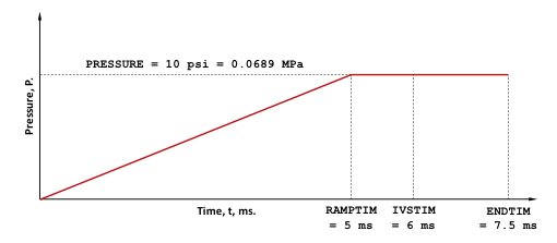
Figure 4.3: Pressure Loading Contitions. Impact Starts at 6 ms and Solution Terminates at 7.5 ms.
Reference
1. Z-2 Prototype Space Suit Development. Amy Ross, Richard Rhodes, David Graziosi, Bobby Jones, Ryan Lee, Bazle Z. (Gama) Haque, and John W. Gillespie Jr. 44th International Conference on Environmental Systems, 13-17 July 2014, Tuscon, Arizona. <link>.
 |
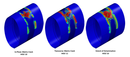 |
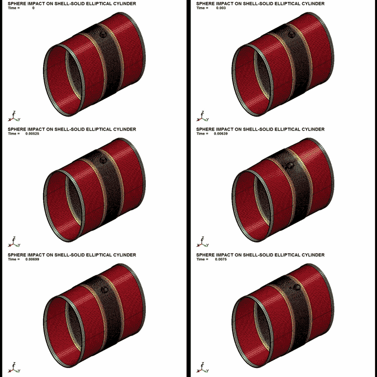
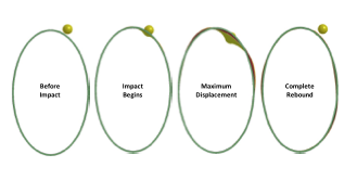
Figure 4.4a: Deformation of the Elliptic-Cylinder under Impact |
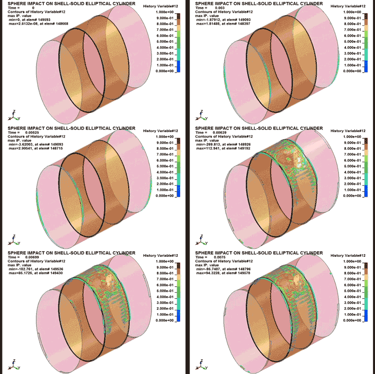
Figure 4.4b: Impact Damage Modes of the [-45] layer at |
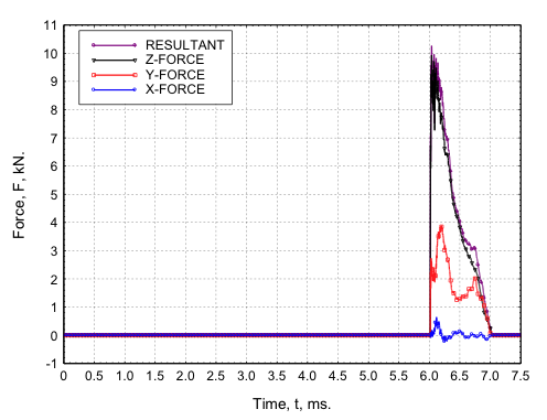
Figure 4.5: X-, Y-, and Z- Components and the Resultant of Impact Contact Force.
| EXAMPLE 4: Elliptic-Cylinder-SHELL-SOLID-MODEL.zip This zip folder contains the following KEWORD files. Run the first file. 001-mmts-Ellipical-Cylinder-SHELL-SOLID.key 002-CONTROL.key 002-README-Elliptical-Cylinder-SHELL-SOLID.key 003-SHELL-SOLID-Elliptical-Cylinder-FEM.key 004-700-Sphere-FEM.key 005-PARTS.key 005-MAT54-Cards-for-T650-5250-5-UD-151-to-154.key 005-MAT162-Cards-for-T650-5250-5-UD-161-to-164.key 006-CONTACT-ERODING-SINGLE-SURFACE-SMP.key 006-CONTACT-ERODING-SINGLE-SURFACE-MPP.key 007-DATABASE.key 007-DATABASE-CROSS-SECTION-PLANE.key 008-BOUNDARY-CONDITIONS.key 009-LOADING-CONDITIONS.key 010-INITIAL-CONDITIONS.key |


